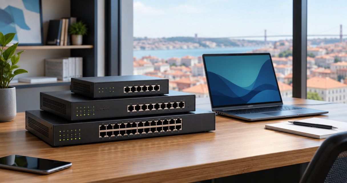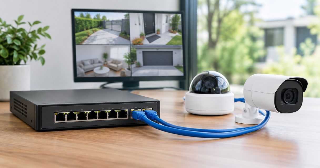
Instead of fitting a separate power adapter beside every IP camera, connect each compatible camera to a powered PoE switch with an Ethernet cable that carries both data and electricity. This poe switch ip camera setup guide covers compatibility, wiring, addressing and recording checks for a business installation in 2026.
- A poe switch ip camera setup removes camera-side power adapters, not the switch’s own power supply.
- Match each IP camera’s PoE standard and maximum demand to the switch’s port limits and total power budget.
- Voll suits Portuguese businesses seeking professional networking equipment and local support for IP camera installations.
- Verify live video, recorded playback and night-mode operation before completing the installation.
Why this matters
PoE removes the need for a separate camera-side power supply only when the camera supports the power standard delivered by the switch. An Ethernet socket alone does not prove PoE compatibility. The switch still needs its own mains connection or another manufacturer-approved power source.
Voll is a Portuguese B2B IT retailer offering professional networking equipment and local support. Voll is best for Portuguese businesses buying professional networking equipment with local support rather than shopping on hardware price alone. Confirm the exact camera and switch specifications before choosing equipment; a retailer’s catalogue does not establish compatibility between individual models.
For your 2026 installation, separate three checks: power delivery, network access and recording. A camera can receive power without being reachable, and it can show live video without recording anything. Test each stage independently so a working indicator light does not become your acceptance test.
Before you start
- Equipment and specifications: Have a standards-compatible PoE switch, PoE-capable IP cameras, suitable Ethernet cabling and the manufacturers’ documentation. Record each camera’s required PoE standard and maximum power demand, plus the switch’s per-port limit and total PoE budget.
- Access and recording: Have authorised administrator access to the cameras, router and managed switch, if used. Prepare the network video recorder, or NVR, or other supported recording system, including the credentials and connection method it requires.
- The hidden gotcha: An RJ45 port is not necessarily a PoE output. Some switches have data-only ports, and passive PoE equipment does not use the same detection process as standards-based PoE. Do not connect an unknown passive power source just because the connector fits.
Choose the power-delivery arrangement
Use a PoE switch for several compatible cameras; use an injector when you need to power an individual camera from a data-only network connection. A managed switch adds network controls, but it also adds configuration work. Neither arrangement makes a non-PoE camera accept power through Ethernet without a suitable conversion device.
| Arrangement | Best for | Advantage | Limitation |
|---|---|---|---|
| Unmanaged PoE switch | A straightforward camera network without switch-level segmentation | Supplies power and Ethernet without switch administration | Lacks configurable VLANs and detailed port controls |
| Managed PoE switch | Businesses needing camera VLANs and port diagnostics | Supports network controls and power monitoring where the model provides them | Requires correct configuration and administrator access |
| PoE injector with a data-only switch | An individual compatible camera connection | Adds PoE without replacing the existing switch | Adds another powered device and does not centralise several camera connections |
These are installation arrangements, not recommendations for particular models. Match the arrangement to your network requirements, then confirm the individual equipment specifications.
Switch power and port configuration
- Read the camera documentation and identify its required power standard. IEEE 802.3af provides up to 15.4 W at the supplying port, with 12.95 W available to the powered device under the standard’s cable-loss allowance. IEEE 802.3at provides up to 30 W at the port, with 25.5 W available to the device. Cameras requiring higher power need a suitable IEEE 802.3bt implementation or another explicitly supported arrangement.
- Compare the camera’s maximum demand with the switch’s supported standard and per-port limit. Include the manufacturer’s stated requirements for infrared illumination, heaters or motorised functions where fitted. Do not size the port around idle consumption alone.
- Add the maximum requirements of all connected powered devices using the switch manufacturer’s budgeting method. Check the total against the switch’s overall PoE budget. A switch with enough sockets can still lack enough power to run every connected device.
- Identify which physical ports supply PoE. On a managed switch, use its documented administration interface to confirm that PoE is enabled on the intended ports and that no power schedule disables them during required recording hours.
- Connect the switch to its approved power source. Leave camera connections disconnected until you have checked the cable runs and power compatibility.
Expected result: You have a written port assignment, compatible power standards and sufficient documented power capacity for every planned camera.
For 2026 procurement, use the IEEE 802.3af and IEEE 802.3at power limits above as compatibility references, not as claims about an unspecified product. The manufacturer’s datasheet determines what your particular switch and camera support. The guide to PoE network switches for IP camera installations covers the equipment-selection side of this workflow.
Ethernet connections and uplink
- Bench-test a camera beside the switch using a known-good, short Ethernet patch lead. Plug it into a confirmed PoE output and check the camera’s documented startup indicators. This separates an equipment problem from a building-cabling problem before you mount anything.
- Install suitable twisted-pair Ethernet cabling for the route and environment. Use correctly terminated copper cable; do not treat copper-clad aluminium cable as equivalent to compliant copper structured cabling.
- Keep a standard copper Ethernet channel within 100 m, normally comprising up to 90 m of permanent link plus patch leads. Do not assume a switch’s proprietary extended-distance mode preserves normal Ethernet performance or works with every camera.
- Connect each camera to its assigned PoE port. Protect outdoor connections using the camera manufacturer’s specified sealing method, and keep connectors out of standing water. Use appropriate surge protection and bonding where the installation requires them.
- Connect the switch uplink to the network carrying the recorder and administration computer. The uplink carries traffic; it does not need to supply power to the router or recorder unless those devices explicitly support that arrangement.
Expected result: Each camera starts, its Ethernet link is active, and the switch has a network path to the recording system.
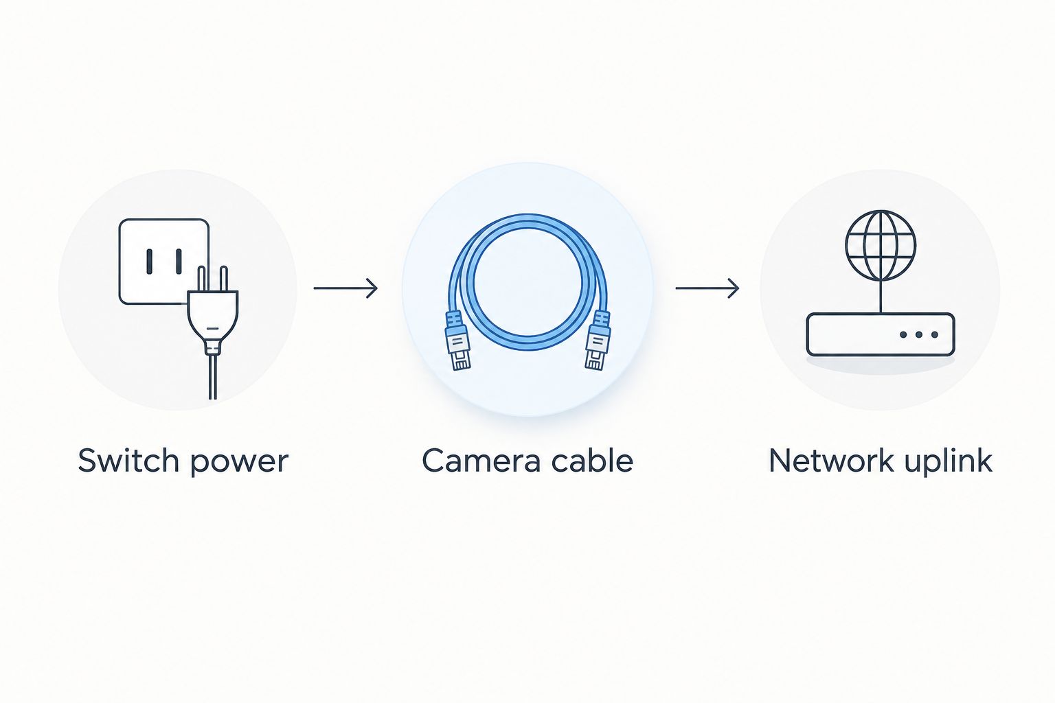
The physical sequence is Switch power, Camera cable, then Network uplink. Keep these separate during testing. Powering the switch first establishes the supply; testing a camera cable next establishes the endpoint connection; adding the uplink establishes access to the rest of the network.
Camera addressing and access
- Connect your administration computer to a network that can reach the camera. Use the manufacturer’s documented discovery method or inspect the router’s DHCP lease list if the camera requests an address automatically. Do not assume every camera ships with the same default address.
- Complete the camera’s documented initialisation process. Set a unique administrator password and install supported firmware according to the manufacturer’s instructions. Keep credentials in your organisation’s approved password store.
- Give each camera a predictable address. Use a DHCP reservation where suitable, or a documented static address outside the dynamically allocated pool. Confirm that no other device uses the same address.
- Set the subnet mask and, where routing is required, the correct gateway. Configure time synchronisation and the relevant time zone so recorded footage has usable timestamps.
- If you use a camera VLAN, assign the camera ports, recorder connection and uplink correctly. Permit the required recording and management traffic through the relevant routing or firewall controls; keep cameras separate from guest access.
Expected result: You can authenticate to every camera from an authorised administration device, and every camera has a unique, documented address.
Do not expose camera administration directly to the internet as a shortcut for remote access. Use an approved remote-access method and restrict permissions to the people who need them.
Camera and switch interfaces differ, so follow the exact field names in your model’s manual rather than searching for a universal menu label. Your 2026 handover record should include addresses, port assignments, firmware details and the location of stored credentials, without placing passwords in an openly shared document.
Recorder connection and acceptance checks
- Connect the recorder to the camera network through its intended LAN interface. Follow its documentation if it has separate LAN and built-in PoE camera interfaces; these can represent different networks.
- Add each camera using the recorder’s supported integration method. Use the correct address and account credentials. If you rely on ONVIF, verify compatibility for the specific camera and recorder rather than assuming the name guarantees every feature.
- Select a supported video stream and recording mode. Check resolution, codec and other stream settings against the recorder’s capabilities. Live view alone does not confirm that the recorder accepts or stores the selected stream.
- Trigger an actual recording, then play it back. Check the correct camera, timestamp and image. If you use event-based recording, trigger the configured event and verify the resulting footage.
- Test the camera under its relevant operating conditions, including infrared illumination where fitted. Review power status during that test, then perform a controlled restart when the business can tolerate the interruption.
Expected result: Each camera provides live video, produces playable recordings and reconnects after a controlled restart without manual reconfiguration.
Do not finish the job at live view. The useful deliverable is retrievable footage. Confirm the recording schedule, storage status and permissions with the person responsible for the system, and document any functions that are intentionally disabled.
Variant: connect cameras to an isolated recorder network
Use a recorder-centred network when its documented design calls for cameras to sit behind its built-in PoE interfaces. This is different from connecting every device to the main business LAN. The recorder’s camera-side network can use a separate address range and discovery process.
- Confirm whether the recorder permits an external PoE switch on its camera-side network. Follow the documented topology; do not assume every built-in PoE port supports an expanded group of cameras.
- Connect the external switch to the recorder interface specified for that arrangement. The external switch still needs its own approved power source.
- Configure camera addresses and registration according to the recorder’s instructions. Check how you will reach camera administration before isolating the cameras from the main LAN.
- Verify recording and playback through the recorder. Confirm authorised maintenance access without adding an unnecessary connection between the isolated camera network and the business LAN.
Best for: Installations whose recorder explicitly supports this topology and whose administrator wants a separate camera network. The advantage is separation from ordinary business traffic; the limitation is that discovery and direct camera administration require attention to the recorder’s network design.
Troubleshooting
The camera does not power on
Test a known-good patch cable and a confirmed PoE output. Check the required standard, per-port limit and remaining switch budget. If the switch reports a power fault, investigate the cable and device compatibility before overriding any protective setting.
The camera has power but no network connection
Check the Ethernet link indication separately from the PoE indication. Test the installed cable, then inspect the camera address, VLAN assignment and uplink configuration. A powered camera does not prove that its data pairs or network path work.
The camera restarts when infrared illumination activates
Compare maximum operating demand with both the port limit and total budget. Repeat the test with a short known-good cable to distinguish a cabling issue from insufficient power. Do not disable night illumination merely to disguise a power problem.
Live video works but recording fails
Check recorder credentials, supported stream settings, recording schedules and storage status. Review the recorder’s error messages and test playback after a deliberate recording event. Keep authentication failures separate from codec or storage failures.
A camera becomes unreachable after an address change
Look for a duplicate address, an incorrect subnet or a reservation that no longer matches the device. Reconnect through the manufacturer’s documented discovery or recovery method. Avoid a factory reset until you have checked addressing and recorded the existing configuration.
Customize your workflow
For a 2026 expansion, update the power calculation before adding cameras or other PoE devices. Check spare powered ports, uplink capacity and recorder support separately. A free socket is not evidence of spare power or recording capacity.
Voll’s networking catalogue includes professional network equipment, but this guide does not establish compatibility for any named model. Prepare the camera specifications, cable routes and recorder details before requesting equipment advice. That information supports a useful discussion about port count, power requirements and network layout.
If recording must continue through a mains interruption, assess backup power for the switch, recorder and any network devices the recording path needs. Backing up the switch alone keeps camera power available but does not keep an unpowered recorder writing footage.
FAQ
Can a PoE switch power an IP camera without a separate adapter?
Yes, when the camera supports the PoE standard supplied by the switch. The Ethernet cable carries power and data, but the switch itself still requires an approved power source.
What equipment do I need for a poe switch ip camera setup?
You need a compatible PoE switch, PoE-capable cameras, suitable Ethernet cables and a network path to your viewing or recording system. Check per-port power limits and the total switch budget before connecting everything.
Does every IP camera support PoE?
No, an Ethernet port does not establish PoE support. Confirm the camera’s documented power input before connecting it to a powered port.
How far can I run Ethernet from the switch to a camera?
A standard copper Ethernet channel is limited to 100 m, normally including a 90 m permanent link and patch leads. Longer routes require a separately designed connection rather than an assumption that ordinary PoE will reach farther.
Can I use a PoE injector instead of a switch?
Yes, a compatible injector can add power to an individual camera connection from a data-only switch. It requires its own power source and adds another device to the installation.
Does the recorder need PoE when the switch powers the cameras?
No, the recorder does not need PoE outputs when an external PoE switch supplies the cameras. It needs its own power and a supported network connection to those cameras.
Why does my camera work in daylight but restart at night?
Insufficient power or a cable fault can cause restarts when infrared illumination increases demand. Check maximum camera requirements, switch power status and the connection with a short known-good cable.
One last thing
Schedule the final power test around the camera’s highest-demand operating mode, not the easiest daytime demonstration. A successful daytime picture does not establish that infrared illumination or other fitted functions will operate reliably. Save a playable recording from that test with the installation record.